Control Cabins
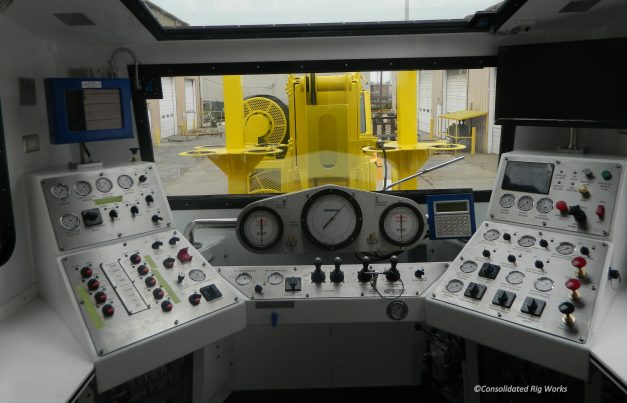
 Control Cabin Console (2015)
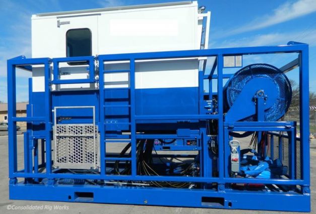
 Standard Control Cabin
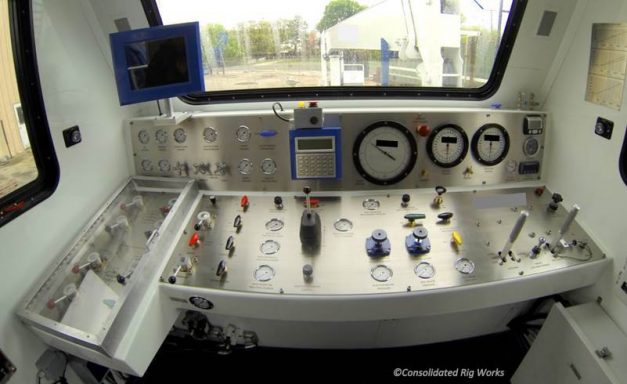
 Control Cabin Console (2014)
CRW Standard Control Cabin Specifications
- Prepped, primed and painted a single color of customer choice.
- Skid fitted with 4-point lift and crash frame
- Maximum dimensions: 196 in. long x 98 in. wide x 102 in. high
- Interior space approx. 113 in. long x 75 in. tall x 77 in. wide
- Elevates via four hydraulic cylinders
- Access provided via platform that folds out beyond protective frame with stairway and handrail
- Cabin fully enclosed and insulated
- Front safety glass window angled for glare reduction and equipped with an air-driven windshield wiper system
- Sliding windows in side panels for ventilation
- Rear window mounted in hinged hatch for emergency exit
- Interior and exterior lighting
- Full-width bench seat with vinyl cover, fold-down desktop, and office chair
- Eye wash bottle and first aid kit mounted near doorway
- Air horn operated from panel
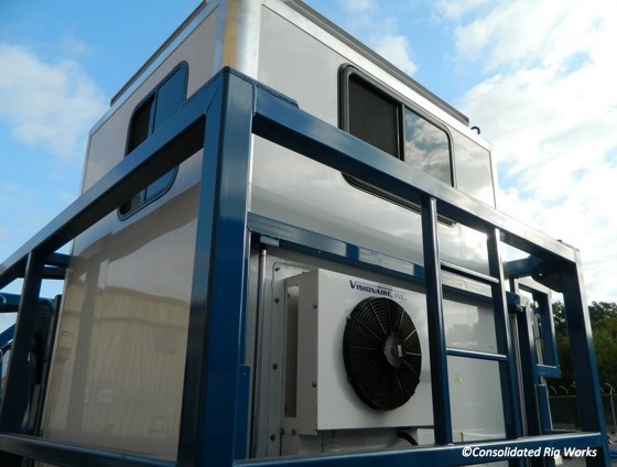
- Hydraulically powered air conditioning system
- Heater system utilizing engine jacket water for heat, located inside booth seat
- Control console, of the “L” shape design, includes the following:
- Stainless steel engraved panel
- Safety cover over BOP ram controls
- Stripper system with relief valve
- Auxiliary hand pump for emergency supply
- Auxiliary air-over-hydraulic pump system
- BOP supply pressure gauge
- Injector traction circuits
- Weight indicator
- Control valve for injector drive pressure
- Control valve for injector speed and direction
- Hydraulic pressure to injector drive gauge
- Injector chain and gear lubricator control valve
- Controls for slow speed injector operation and a high/low speed selector valve
- Pressure control valves and gauges for injector outside chain tensioning control
- Red control valve button for the injector emergency brake
- Selector valve for two-speed or variable speed injectors
- Control valve to control injector motor displacement
- 3-bank hydraulic valve to control reel pay-off or take-up and levelwind override
- Levelwind raise or lower
- Relief valve to control reel tension
- Reel drive pressure gauge.
- Manual valve for reel brake control
- Reel brake pressure gauge
- Safety latch on directional control valve handle for reel direction
- Wellhead pressure and circulating pressure gauges
- Control hoses plumbed into bulkhead panels with QD’s, where required
- Engine monitoring system and pneumatically operated emergency engine air shut-off
- Hose reels and hoses:
- One hydraulically powered hose reel for injector control hoses and one hydraulically controlled hose reel for BOP control hoses, both fire resistant for the last 50 feet, and equipped with multiple-port hydraulic rotating swivels for direct connection to the bulkhead panel.
- Control hose reel skids, forklift removable for remote operation.
- Two hose bundles with 25 ft. of power pack and tubing reel control hoses installed in the cabin skid for easy access
- Control hoses with QD’s, with caps and plugs firmly secured to the hoses
- Hose bars installed at the end of all hoses bundles. Injector and BOP hose bundles provided with chain support.
- Hose bundles covered with oil-resistant jacketing and securely tied, with identifying washer on ends.
- Hose reel flange areas include protective cover to prevent operator hand traps between reel spoke and support structure.
Alternative Control Cabin Specifications
CRW also offers a smaller (60”x 60”x72”) aluminum cabin insulated with foam sheeting. Cabin is mounted to a steel skid with lift cylinders for improved operator vision, and ISO corner locking blocks for ease of transport. Wrapping posts are provided at the front of the control cab skid for the tubing reel and power pack hoses. The two multi-port hose reel assemblies for BOP and injector are also mounted to this skid, pinned for ease of removal. The unit is provided with a hydraulically driven A/C-heater assembly. AC voltage, plug for power to cabin provided (pigtail end for splicing mating cord). Complete console assembly inclusive of all valving, gauges and connections to operate and run the coiled tubing and pump components.


